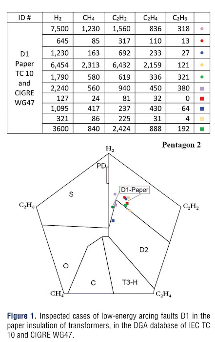
We use Pentagons 1 and 2 in the new CIGRE and IEEE Gas Guides to interpret DGA in transformers and other electrical equipment. These pentagons are used as complements to the Duval Triangles 1,4, and 5 which were developed earlier.
These triangles and pentagons allow for the easy visual identification of gas formation patterns that occur during the service life of a transformer, some under normal operating conditions and others when some electrical and thermal abnormalities start forming in the transformer system. Specific types of faults produce specific gas formation patterns. Therefore, after extensive research and database analysis, Dr. Duval came up with the triangles and pentagons to assist in the visual diagnostic of several abnormalities that might occur during the lifetime of a transformer, i.e. Electrical and thermal faults, corona partial discharge (PD), Low-energy arcing (D1), High energy arcing (D2), high-temperature faults in oil only (T3-H), possible carbonization of paper (C), overheating (O), and stray gassing in oil (S).
Low and high energy faults in transformers have been defined in IEC 60599 section 5.2 [2]
"... discharges of low energy (D1), in oil or in the paper, evidenced by larger carbonized perforations through paper (punctures), carbonization of the paper surface (tracking) or carbon particles in oils (as in tap diverter operation); also, partial discharges of sparking type, inducing pinholes, carbonized perforations (punctures) in the paper, which, however, may not be easy to find."
"...discharges of high energy (D2), in oil or in paper, with power follow-through, evidenced by extensive destruction and carbonization of paper, metal fusion at the discharge extremities, extensive carbonization in oil and, in some cases, tripping of the equipment, confirming the large current follow through."
Some inspected cases of arcing faults D1 and D2, published by IEC TC 10 [3], or as presented in meetings of CIGRE WG A2/D1.47 [1], have been separated according to the location of the arcing - either paper or oil. If it was not certain where the problem was located, the readings were discarded and not used as part of the reference data model. The data sets that remained were plotted in the pentagons, in the figure attached only 10 cases were plotted for clarity.
Gases in the tables within the figures are Hydrogen (H2), Methane (CH4), Acetylene (C2H2), Ethylene (C2H4), and Ethane (C2H6). All the cases plotted have been visually identified and were validated afterward.
Arcing Faults D1 and D2, in the paper insulation of the transformer.
D1 Faults - Low energy arcing
D2 Faults - High energy arcing faults in paper insulation
Reference:
[1] CIGRE D1/A2.47, "Advances in DGA interpretation," CIGRE Technical Brochure #771, Paris, France: CIGRE Jul 2019.
[2] Mineral Oil-Impregnated Electrical Equipment in Service-Guide to the Interpretation of Dissolved and Free Gases Analysis, IEC Standard 60599, 2015
[3] M. Duval and A. de Pablo, "Interpretation of gas-in-oil analysis using new IEC publication 60599 and IEC TC 10 databases," IEEE Electr. Insul. Mag., vol 17, no 2, pp 31-41.


No comments:
Post a Comment