There are three main sources of excessive moisture in a transformer

Residual Moisture

Even after the transformer core's drying, there might still be some residual moisture in some parts. These are usually in the more significant parts like wood, plastic, and resin-impregnated parts. These would need much longer drying times than cellulose paper and pressboard. The laminated pressboard is glued together with strips of pressboard. This will dry parallel to the layer direction; the glue prevents perpendicular drying. 
 
When the transformer starts operating, the moisture will migrate from these parts with the high moisture content to part of the core with lower moisture content. It will also move into the oil eventually. This is a lengthy process, and this will happen in a few weeks. This process will continue until the entire system

has reached an equilibrium point. This equilibrium point will depend on the unit's operating temperature as well as the total moisture content of the insulating system, the oil, and the core. 
 
  • Please note that the core can only be dried out in the oven for a limited time, as the paper will start to crack and decompose if all the moisture is taken out of the structure. 

Moisture ingress

There are three mechanisms for moisture ingress from the atmosphere. 

Direct exposure

This will occur when the transformer insulation is exposed to air - during the installation and repair processes. 

Molecular flow (Knudsen flow)

This type of flow will occur when there is a difference in water vapor pressure in the atmosphere and the transformer gas space or oil. This term describes the diffusion of gases through a tiny opening, like a gasket that does not seal completely. [1,2]

Viscous flow

This will happen when there is a difference in total pressure when the atmospheric pressure is higher than the tank's pressure. This will happen through the conservator system of free-breathing units. 


The main points to remember

The molecular flow will have a negligible influence on the moisture of the system.

The primary mechanism through which water will penetrate the system is through low seals by the flow of wet air into the unit because of higher air pressure outside the tank. Typical leaks that will allow this phenomenon would be at the top gasket seals at the explosion vent and forced oil-cooled units between the main tank and the coolers. Although no oil leaks are visible, there might be an ingress of atmospheric air. In water-cooled systems, water might penetrate the cooler into the oil, even if it is at a higher pressure. 

Large amounts of rainwater can be sucked into the transformer in a concise time (several hours) when a rapid drop in pressure on the inside of the tank occurs ( this can be induced by rain) in combination with insufficient sealing. This becomes a real problem when transformers are stored with some oil without the conservator preservation system. 

The contamination rate with moisture is significant for free-breathing transformers with conservator tanks, although it is limited. 

Research has shown that transformers with free-breathing systems have a moisture contamination rate of up to 0.2% per year. Most of this water is retained in wet zones and not evenly distributed throughout the complete system. It was found that only about 0.5 to 0.6 % of water is extracted from the cellulose insulation during the drying process, even if the water content can be as high as 2.5% in thin cellulose structures. 

The water contamination rate for units with membrane-sealed conservator systems is only about 0.03-0.06% water in the cellulose material.

Units with broken seals or insufficient sealing have over 50kg of free water from both open-breathing and membrane-sealed conservator systems. The damaged heat exchanger can be the source of substantial amounts of water moving into the oil in a water-cooled transformer. 

Opening a transformer and exposing its core will cause more considerable water ingress into the cellulose system than a unit with an imperfect preservation system will display after many years.

This table is sourced from [1]

Moisture Contamination during exposure of the active parts to the atmosphere

The transformers' outer insulation layers quickly absorb moisture, but the diffusion of these moisture molecules into the inner layers will take a long time.

The air's relative humidity is critical because it will determine the moisture absorbed by the insulating material.

95% of the absorbed moisture will be confined to the insulation with depths of 0.3 to 0.35 mm. Moisture is concentrated in the outer layers of the insulation components.

References:

  1. V. Sokolov, B. Vanin, Evaluation of Power Transformer Insulation Through Measurement of Dielectric Characteristics, Proceedings of the sixty-third Annual International Conference of Doble Clients, 1996, sec 8-7
  2. V Sokolov, B Vanin, In-Service Assessment of Water Content in Power Transformers. Proceedings of the sixty - second Annual International Conference of Doble Clients, 1995, sec 8-6
  3. V. Sokolov, Methods to improve Effectiveness of Diagnostics of Insulation Condition in Large Power Transformers. Ph.D. Thesis, The Technical University of Kiev, 1982 (in Russian)
 

Influences on the load ability and lifetime of distribution transformers due to harmonic current content and ambient temperature - part 1

 Background

Recently, the effect of harmonic current content and ambient temperature has been linked to many of the failures seen in distribution transformers. The reason is the increase in transformer losses due to increased harmonics, specifically current harmonics. An increase in the harmonic content of the load current will create extra losses in windings, leading to an increase in hot spot temperatures and in the stress on the insulation of the transformer. These above-mentioned factors will decrease the useful life of the transformer due to the decrease of the useful life of the insulation and the transformer's loading capacity. 

Introduction

Distribution transformers are typically created to provide power to devices that require a consistent and steady electrical current. However, there are instances where the voltage and current can become distorted due to non-linear loads, resulting in an increase in harmonics and other irregularities. In the past, non-linear loads made up only about 15% of the total power consumption, but in the year 2000, this number increased to 50%. As a result, the presence of non-linear loads leads to a higher harmonic content in the network. This increased non-linear load has many disadvantages such as an increase in the loss and reduction of the efficiency of power system equipment. Therefore, the impact of harmonics on the loss of useful life and reduction of efficiency in power transformers needs to be investigated. The reduction of life in transformers can be due to hot spot temperatures in the transformer winding, and this increased temperature can be a direct effect due to harmonic presence. The hot spot temperature is in direct correlation to the winding temperature and top oil temperature which is an important parameter to ensure efficient transformer monitoring. One of the most limiting factors in transformer loading is the hot spot temperatures. To evaluate loading ability awareness, the hot spot temperature is required. Thermal stresses are one of the most important factors influencing insulation deterioration, therefore hot spot temperature data are crucial to ensure better evaluation of the loading ability of a transformer, the used lifetime as well as the determination of the possible remaining lifetime of the transformer. 

At an IEEE Transformers Committee meeting in March 1980, it was recommended that a standard is provided for guidance in estimating the loading capacity of the transformer in a network with distorted currents. After this, IEEE C 57.110 entitled "Recommended procedure for determination of the transformer capacity under non-sinusoidal load currents" was published. This standard determines the procedure to decrease the level of the rated current for risen harmonics. 

Instruction for the application of Duval Pentagons in fault diagnostics for oil filled transformers.

 We use Pentagons 1 and 2 in the new CIGRE and IEEE Gas Guides to interpret DGA in transformers and other electrical equipment. These pentagons are used as complements to the Duval Triangles 1,4, and 5 which were developed earlier. 

These triangles and pentagons allow for the easy visual identification of gas formation patterns that occur during the service life of a transformer, some under normal operating conditions and others when some electrical and thermal abnormalities start forming in the transformer system. Specific types of faults produce specific gas formation patterns. Therefore, after extensive research and database analysis, Dr. Duval came up with the triangles and pentagons to assist in the visual diagnostic of several abnormalities that might occur during the lifetime of a transformer, i.e. Electrical and thermal faults, corona partial discharge (PD), Low-energy arcing (D1), High energy arcing (D2), high-temperature faults in oil only (T3-H), possible carbonization of paper (C), overheating (O), and stray gassing in oil (S). 

Low and high energy faults in transformers have been defined in IEC 60599 section 5.2 [2] 

"... discharges of low energy (D1), in oil or in the paper, evidenced by larger carbonized perforations through paper (punctures), carbonization of the paper surface (tracking) or carbon particles in oils (as in tap diverter operation); also, partial discharges of sparking type, inducing pinholes, carbonized perforations (punctures) in the paper, which, however, may not be easy to find."

"...discharges of high energy (D2), in oil or in paper, with power follow-through, evidenced by extensive destruction and carbonization of paper, metal fusion at the discharge extremities, extensive carbonization in oil and, in some cases, tripping of the equipment, confirming the large current follow through."

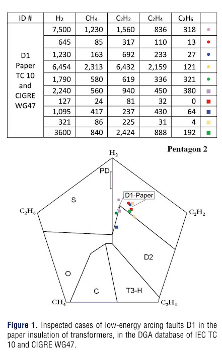
Some inspected cases of arcing faults D1 and D2, published by IEC TC 10 [3], or as presented in meetings of CIGRE WG A2/D1.47 [1], have been separated according to the location of the arcing - either paper or oil. If it was not certain where the problem was located, the readings were discarded and not used as part of the reference data model. The data sets that remained were plotted in the pentagons, in the figure attached only 10 cases were plotted for clarity. 

Gases in the tables within the figures are Hydrogen (H2), Methane (CH4), Acetylene (C2H2), Ethylene (C2H4), and Ethane (C2H6). All the cases plotted have been visually identified and were validated afterward. 

Arcing Faults D1 and D2, in the paper insulation of the transformer.

D1 Faults - Low energy arcing


D2 Faults - High energy arcing faults in paper insulation


Reference:

[1] CIGRE D1/A2.47, "Advances in DGA interpretation," CIGRE Technical Brochure #771, Paris, France: CIGRE Jul 2019.

[2] Mineral Oil-Impregnated Electrical Equipment in Service-Guide to the Interpretation of Dissolved and Free Gases Analysis, IEC Standard 60599, 2015

[3] M. Duval and A. de Pablo, "Interpretation of gas-in-oil analysis using new IEC publication 60599 and IEC TC 10 databases," IEEE Electr. Insul. Mag., vol 17, no 2, pp 31-41. 

Distinguishing arcing faults in paper from those in oil in transformers


 Introduction


Identifying faults in oil-filled transformers is mainly done by applying the dissolved gas analysis (DGA) method. In 2019 CIGRE published a technical bulletin TB 771 [1], which explains advanced techniques for DGA interpretation this method takes into account the type and location of the faults to establish acceptable and dangerous levels of gas present in the transformer. 

To accurately determine the location of arcing faults, (in oil or paper), TB 771 recommends the use of acoustic levels, CO2/CO ratios as well as the furan content of the oil. Acoustic tests might however be unavailable, too expensive, or might pose a risk due to the arcing. 

The CO2/CO ratio can be misleading in many instances as it is influenced by various factors such as the oxidation of oil in sealed units [2], normal aging of paper, and to a very small degree by the arcing. 

Thirdly, arcing faults might not produce a high concentration of furans to be detectable. [1]

Cases of transformer arcing were studied as per the available databases at IEC [3] and CIGRE [2] to see if there is the production of specific gases in the fault zones D1 and D2 of the Duval Pentagon 1 or 2. The method described below is a new diagnostic tool made available by Michel Duval and Jerzy Buchacz and forms part of the diagnostic toolbox provided by the Duval Pentagons. This method provides an early warning of a serious fault involving arcing in the paper. 


Arcing faults D1 and D2 in the paper insulation of transformers


                   Fig 1: Paper failure of the transformer core due to electrical fault.


Nobody wants this to be their transformer. 

Table 1 is actual data taken from the IEC TC 10 [3] and CIGRE WG 47 [1] database of cases of low energy arcing faults, D1 in the paper insulation of transformers. 


In Figure 2 the inspected cases of high-energy arcing faults D2 in the paper insulation are plotted as per IEC TC [3].


Arcing faults D1 and D2 in the Oil of Transformers

Cases of low-energy arcing faults D1 in the oil of transformers in DGA are plotted in Figure 3, based on data from the IEC TC 10 [3] database.


Cases of high-energy arcing faults, D2 in oil of transformers are plotted in Figure 4, this is based on data from the IEC TC 10 [3] database. 


The cases of low-energy arcing faults, D1 in the oil, in the DGA database of CIGRE WG 47, occur in the same area as Zone D1 as in Figure 3. However, they are not included here.

Arc-Switching in the Oil of On-Load Tap Changers

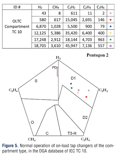
Under normal operating conditions, oil-type on-load tap changers (OLTCs) will involve arc-switching. Therefore they can serve as good examples of arcing taking place in oil because there is no paper present in the on-load tap changer compartment. Figure 5 represents the cases as identified "normal operation" for the OLTCs of the compartment type, data from the IEC TC 10 of 2002 [7] were used. 


New Sub-Zones of Pentagons 1 and 2 for Arcing Faults D1 and D2 in the Paper Insulation of Transformers.

When we compare Figures 1 to 5, it is clear that the arcing faults in the paper insulation and in the oil occur in different sub-zones of Pentagons 1 and 2. These new sub-zones are indicated in Figure 6. 


The symbol (-H) was used in Pentagon 2 [6] to high-temperature faults, T3, in oil only thus (T3-H). (-H) was assigned to Figure 6 to indicate arcing faults - D1 and D2 in oil, thus (D1-H) and (D2-H), the continuation of the same symbol ensures consistency and ease of interpretation. To indicate arcing faults in Paper, the symbol (-P) was used. This is then indicated as (D1-P) and (D2-P) on Pentagon 2. If the gas formation indicates an area in sub-zone D1-P or D2-P of Figure 6, it might be very possible that the arcing fault is in the paper, but this is not 100% certain, it might be that a few arcing faults present in oil might show up in these areas. 

Arcing faults in paper will never show up in D1-H and D2-H, no false negatives were reported for these regions. It was noticed that the on-load tap changers of the in-tank type (MR) might often produce gases in the D2-H sub-zone.

It is advised that the arcing faults in the paper should be confirmed by other observations, like acoustic tests and CO2/CO rations. As mentioned previously, the CO2/CO ratio might be misleading because of the influence of other factors apart from arcing.[2] Acoustic tests are more efficient but less sensitive to arcing faults inside the coil due to the high attenuation of acoustic signals by the winding and insulation barriers. 

It is quite important to differentiate between an arcing fault in the oil and one in the paper due to the practical implications. It has been shown by CIGRE [1] that the dangerous (pre-failure) concentration value of C2H2 ( Acetylene) in the case of arcing faults D1 in oil is 1400 ppm, whereas it is only 45 ppm for arcing faults D1 in paper. This can cause a major failure if the diagnostician does not differentiate correctly between the two scenarios. 

Conclusion

As per Figure 6, new sub-zones have been identified in the Duval Pentagons. This amendment allows for the identification of arcing faults D1 and D2, in the paper or in the oil as this differentiation is crucial to ensure accurate diagnostic results to the customer. This was previously only possible through expensive acoustic testing, or somewhat unreliable CO2/Co ratios. 

This enables maintenance efforts to concentrate on the units that are identified as critical due to arcing in the paper. This scenario is in the minority but potentially extremely dangerous. Arcing in oil is much more common and not as concerning from an asset reliability viewpoint, depending on the location of the fault and the gas production rate. In some cases arcing in oil might be of concern and would require further investigation. 


References:

[1] CIGRE D1/A2.47, "Advances in DGA interpretation." CIGRE Technical Brochure # 771, Paris, France: CIGRE, Jul 2019

[2] Mineral Oil-Impregnated Electrical Equipment in Service Guide to the Interpretation of Dissolved and Free Gases Analysis, IEC Standard 60599, 2015.

[3] M. Duval and A. de Pablo, " Interpretation of gas-in-oil analysis using new IEC publication 60599 and IEC TC 10 databases." IEEE Electr. Insul. Mag., Vol 17, no 2, pp 31-41, https://ieeexplore.ieee.org/document/917529 , 2001.

[4] Guide for the Interpretation of Gases Generated in Mineral Oil-Immersed Transformers, IEEE Standard C57.104-2019.

[5]M Duval and L. Lamarre, "The Duval Pentagon - A new complementary tool for the interpretation tool for the interpretation of dissolved gas analysis in transformers," IEEE Electr. Insul. Mag., vol 30, no. 6, pp 9-12, https://ieeexplore.ieee.org/document/6943428 , 2014

[6] M. Duval, "Use of Duval Pentagons and Triangles for the interpretation of DGA in electrical equipment." presented at the TechCon North America Conf., Albuquerque, NM, 2016.

[7] M. Duval, " A review of faults detectable by gas-in-oil analysis in transformers." IEEE Electr. Insul. Mag, vol 18, no 3, pp 8-17. https://ieeexplore.ieee.org/document/1014963


There are three main sources of excessive moisture in a transformer

Residual Moisture Even after the transformer core's drying, there might still be some residual moisture in some parts. These are usually...